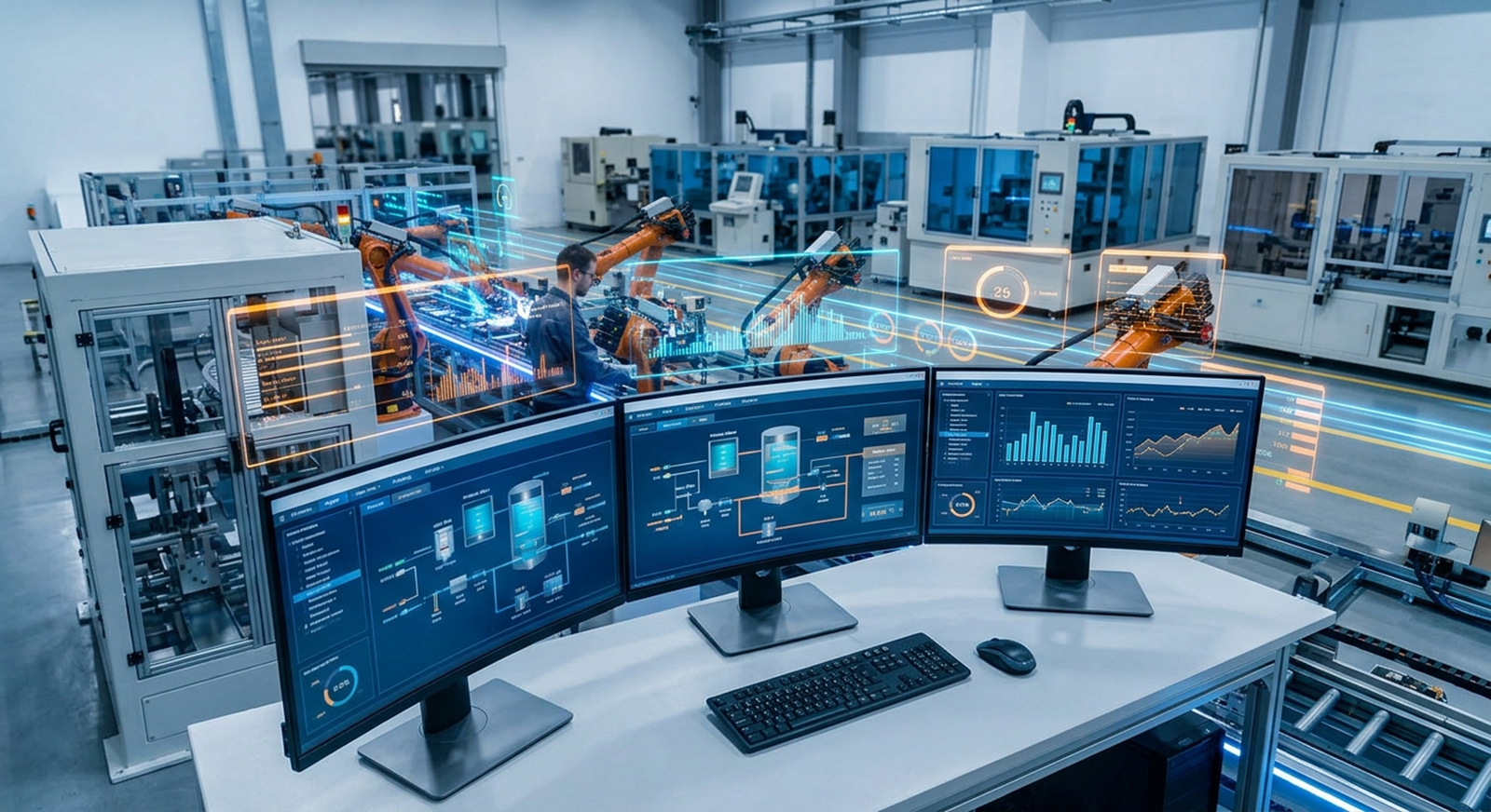
Industrial automation is a coordinated control loop that connects the physical process to decisions, motion, operator information, and maintenance data. A typical system senses a condition, evaluates it in a controller, commands an actuator, and checks the result through feedback.
That loop sounds straightforward, but reliable automation depends on the details between each step: electrical design, safety boundaries, sequence logic, device configuration, network behavior, and commissioning. This guide follows a realistic machine cycle from a sensor changing state to a completed operation.
1. Sense the process
Inputs tell the control system what is happening. A photoeye may detect a product, an encoder may measure position, and a pressure or temperature transmitter may report a process value. Limit switches, proximity sensors, valve feedback, drive status, and safety devices provide additional conditions.
The signal must be physically sound before software can interpret it. Sensor selection, wiring, voltage, shielding, input type, scaling, and installation all affect the value seen by the PLC. A sensor that is misaligned or wired to the wrong module can look like a logic problem.
2. Decide in the controller
The PLC evaluates inputs and internal state against the programmed sequence. It may decide that a conveyor can run only when guards are closed, downstream equipment is ready, a drive is healthy, and a start request is present. It may also manage step transitions, timers, recipes, interlocks, fault recovery, and communication with other devices.
Safety functions are treated as their own engineering responsibility. Depending on the machine, emergency stops, guard switches, light curtains, and safe motion may use safety relays, a safety PLC, or safety-rated drive functions. Standard PLC logic should not be presented as a substitute for a properly designed safety circuit.
3. Actuate the machine
Outputs turn decisions into physical action. A PLC can command a solenoid valve, contactor, relay, VFD, servo system, robot permit, or pneumatic sequence. The final device still has its own requirements. A drive needs valid motor data and a control source; a robot needs the right mode and handshake; a valve needs air supply and feedback where required.
Good automation does not merely energize an output. It confirms that the commanded action happened, applies timeouts, and creates a useful fault when it did not. That distinction is the difference between a machine that stops with an explanation and one that leaves maintenance guessing.
4. Supervise and inform
The HMI gives operators a local view of modes, states, alarms, recipes, production counts, and recovery instructions. SCADA can collect information from multiple machines for trends, reports, and plant-level visibility. Neither should hide the underlying PLC state.
Useful alarms identify the failed condition and its location. “Motor fault” is a starting point; “Conveyor 2 drive fault: check drive status and reset after cause is cleared” is more actionable. Alarm history and timestamps help distinguish a primary failure from the secondary faults that follow it.
Example: a conveyor loading cycle
- A photoeye detects a tote entering the load position.
- The PLC verifies the guard circuit, downstream ready signal, and drive permissive.
- The PLC commands the conveyor drive to stop and waits for stopped feedback.
- A cylinder extends, and a sensor confirms the expected position within a timeout.
- The PLC records the step complete, updates the HMI, and releases the tote.
Each transition needs a normal path, a timeout, and a recovery decision. Commissioning should test missing sensors, blocked motion, communication loss, and restart behavior instead of testing only the ideal cycle.
Why integrated design matters
Projects become difficult when the panel, program, mechanical sequence, and operator interface are designed in isolation. The I/O list must match the actual field wiring. Device addresses must match the controller configuration. HMI messages must reflect real machine states. The commissioning plan must cover the conditions the operators will actually encounter.
For a deeper comparison of system layers, read PLC vs HMI vs SCADA. TechControl supports control panel design, PLC and HMI programming, machine commissioning, and troubleshooting as connected parts of the same system. See our process for how that work is organized.
Ready to bring your project to life?
Contact Us