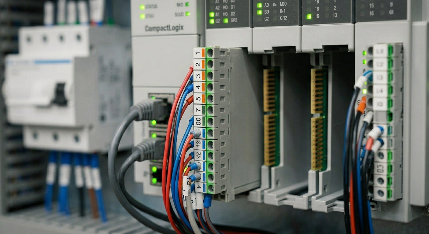
PLC inputs and outputs, often called I/O, are the boundary between controller logic and the physical machine. Inputs tell the PLC what sensors and devices report. Outputs allow the PLC to command valves, contactors, lamps, drives, and other equipment.
Digital inputs
Digital inputs represent on/off states: a photoeye blocked, a guard switch closed, a pressure switch made, or a pushbutton pressed. Voltage, common reference, polarity, sinking/sourcing arrangement, and module type must all match the electrical design.
Digital outputs
Digital outputs command discrete devices. An output module may drive a relay, solenoid, contactor coil, or interposing relay, but its voltage and current rating must suit the load. An output LED being on does not prove that the load has power or that the actuator moved.
Analog inputs and outputs
Analog signals represent a range. Common examples include 4–20 mA pressure, 0–10 V speed reference, and temperature transmitter values. The raw signal must be configured and scaled into engineering units. Incorrect range selection or scaling can create a convincing but wrong process value.
Remote and networked I/O
Remote I/O reduces wiring distance but adds adapters, network addresses, connection settings, and device diagnostics. A controller may be healthy while one remote adapter or module is faulted. For field diagnosis, see PLC I/O troubleshooting.
I/O documentation
- Record terminal, channel, device, voltage, and tag name.
- Document normal and fault states.
- Identify whether an input is safety-related.
- Keep the online configuration aligned with drawings.
TechControl supports I/O mapping and PLC programming for existing and new control systems. See What is a PLC? for the larger controller context.
Ready to bring your project to life?
Contact Us